Hydraulics is the study of water or liquid at rest or in motion. Some common terms used when discussing hydraulics are defined below, along with their standard units of measurement.
Velocity
Velocity is the average speed at which water moves through a certain cross section or past a certain point. This is usually measured in kilometres per hour (km/h) and metres per second (m/s) in the metric system and miles per hour (mph) and feet per second (fps) in the Imperial system.
Flow Rate
The flow rate is the measurement of water or liquid that flows through a conduit or pipe during a certain time period. This is usually measured in litres per second (L/s), cubic metres per second (m3/s) and megalitres per day (ML/d) in the metric system or gallons per day (gpd) in the Imperial system.
Rate of flow may be calculated by multiplying the velocity of the fluid by the cross-sectional area at right angles to the direction of flow.
Flow Rate = A X V (A=Area V=Velocity)
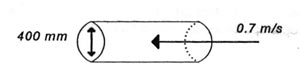
Example 1: Calculate the flow rate in a 400 mm diameter pipe if the velocity is 0.7 m/s.
(1) Calculate cross-sectional area of pipe.
 /4
/4
= 3.1416 X (0.4m)
= 0.126 m2
(2) Calculate the flow rate.
Flow Rate = A X V
= 0.126 m2 x 0.7 m/s
= 0.088 m3/s
Example 2: Calculate the flow rate (m3/s) through a rectangular channel with a width of 3 metres and a depth of 2.1 metres. The water has a velocity of 0.5 m/s.
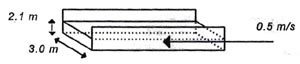
3m X 2.1m X 0.5 m/s
=3.15 m3/s
Measuring Flow Rate
Flow rate is one of the most important measurements which an operator uses. This measurement will provide information on the detention times in tanks, flow between various processess or sections of a distribution/collection system, chemical feed rates, amount of water treated/pumped, costs of treatment, and the need for system expansion. There are numerous methods for measuring flow rate. The types of measurement are dependent on whether the water is flowing in a closed pipe or in an open channel. Open channels are measured using weirs or flumes. A weir is a dam or obstruction in the channel. A flume is a specifically shaped constriction in the channel. In both cases the flow rate is related to the height of water at a particular point. Some of the common methods of measuring closed pipes include venturi meters, ultrasonic meters, magnetic meters, Doppler meters and orifice meters. Although flow meters are vital in the operation of a system, their usefulness depends on proper operation, calibration and maintenance.
Pressure and Head
When water flows through a system under force, that force measured per unit of area is termed pressure. Pressure is usually measured in kilopascals (kPa) in the metric system and pounds per inch (psi) in the Imperial system. Static pressure refers to the force exerted when water is at rest and not flowing. Pressure exerted by flowing water is known as dynamic pressure.
It is often more convenient to express pressure in terms of a height of a column of fluid of constant unit weight. Therefore, the pressure at the bottom of a water column depends directly, and only, on the height of the column. When pressure is expressed in this way it is commonly referred to as pressure head. The head may be expressed in terms of feet of water column or inches of mercury in the Imperial system, or metres in the metric system.
Pressure can be measured using pressure gauges (a Bourdon pressure gauge is the most common) or with the use of manometers.
Friction Loss in Pipes
Friction occurs whenever there is flow through pipes. Friction causes a loss of head. Friction looses depend on the velocity or rate of flow, the length and size or diameter of a pipe and the apparent roughness of the pipe surface contacting the water. For a particular pipe, the larger the pipe diameter or the smoother the interior pipe surface, the lower the head loss loss due to friction. Fot this reason, pipe size will influence the velocity at which the water can flow through the system. If all else is equal (i.e. smoothness, pipe material and head) the smaller the pipe diameter the higher the velocity. As velocity increases friction losses increase, reducing the pressure at the outlet. This friction loss must be made up by way of higher energy inputs (for example additional pumping).
Water hammer
When operating a distribution system it is important to understand the effects of pipe size and water hammer. As velocity increases friction losses increase, reducing the pressure at the outlet. This friction loss must be made up by way of higher energy inputs.
Water hammer occurs when a moving fluid is suddenly stopped. The energy which must be absorbed within the system can create pressures which will destroy the piping and appurtenances. One can think of water hammer like a speeding train which is forced to stop very suddenly. Although the locomotive stops in its tracks the cars which follow derail since their energy cannot be absorbed by the train. To avoid water hammer, valves must be operated very slowly. Operators must be aware of situations where water hammer can have costly or disastrouc effects.
Cavitation
When operating pumps it is important to follow the pump directions. Cavitation can occur as a result of very low pressure within a pump. This low pressure causes the water to boil, releasing tiny bubbles. The bubbles will then collapse, with enough force to damage the pump impeller. Cavitation can be avoided if the pump capacity, speed, head and suction lift are properly determined. Cavitation can cause rapid damage to the impeller of a pump. A noise, similar to hammering of the pump impeller, will indicate to the operator that cavitation is occurring.