
Jess Stryker's Landscape Sprinkler Design Tutorial
Irrigation Pumping Systems
 |
Jess Stryker's Landscape Sprinkler Design Tutorial |
If you're thinking of installing a new pump, or just want to understand your existing pumping system better, this page should provide you with the information you need to get started.
Pumping Purpose
You may not need a booster pump, but you're going to run into that term now and then, so let's start by defining it. Most pumps are used to take water from a standing (or non-pressurized) source and move it to another location. For example, a pump might take water from a lake and move it to a sprinkler system. A booster pump, on the other hand, is used to increase the water pressure of water that is already on its way somewhere. Example; say you have a sprinkler system that needs 80 PSI of pressure to operate. But the water line coming onto your property only has 50 PSI of pressure. In this cases you would install a booster pump to raise the pressure from 50 PSI up to 80 PSI for your sprinkler system. So to put it another way, a booster pump is used to "boost" the water pressure. Any of the types of pumps listed below can be used as a booster pump (but almost all booster pumps are the "end-suction centrifugal" type).
Types of Pumps
Irrigation pumps fall into the following categories based on the design of the pump. This tutorial addresses electric powered pumps only. While most of the information here also applies to fuel powered pumps the formulas don't! You must use different formulas for calculating the size and flow information for fuel powered pumps. If you have an engine powered pump (gas, diesel, propane, corn liquor, etc.) you should contact the pump manufacturer ad request a copy of the pump performance curve.
Displacement Pumps.
Displacement pumps force the water to move by displacement (bet you couldn't have guessed!) This means pumps such as piston pumps, diaphragm pumps, roller-tubes, and rotary pumps. These pumps are used for moving very thick liquids, or creating very high pressures. They are used in fertilizer injectors, spray pumps, air compressors, and hydraulic systems for machinery. With the exception of fertilizer injectors (used for mixing fertilizer into irrigation water) you will not see them typically used for irrigation systems, so that is all I'm going to say about them
Centrifugal Pumps.
Almost all irrigation pumps fall into this category. A centrifugal pump uses an "impeller" (sort of like a propeller, but a little different) to spin the water rapidly in a "casing", "chamber", or "housing" (any of those terms may be used). This spinning action moves the water through the pump by means of centrifugal force. Centrifugal pumps may be "multi-stage", which means they have more than one impeller and casing, and the water is passed from one impeller to another with an increase in pressure occurring each time. Each impeller/casing combination is referred to as a "stage". All centrifugal pumps must have a "wet inlet", that is, there must be water in both the intake (inlet) pipe and the casing when the pump is started. They can't suck water up into the intake pipe like you can suck soda up into an empty straw. They must be "primed" before the first use. To prime them you simply fill the intake pipe with water and then quickly turn on the pump. To put it simply, this type of pump can't suck air, only water, so if there is no water already in the pump it won't pull any water up into it. Once it gets water in it the first time, most centrifugals are designed to hold the water with a small valve so the pump doesn't need to be primed again every time you turn it on.
Types of Centrifugal Pumps:
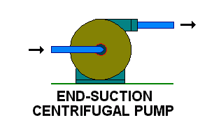
End-Suction Centrifugal. The most common type of pump. Typically the pump is "close-coupled" to an electric motor, that is, the pump is mounted right on the end of the motor's drive shaft and the pump case is bolted straight into the motor so that it looks like a single unit. The water typically enters the pump through a "suction inlet" centered on one side of the pump, and exits at the top. Almost all portable pumps are end-suction centrifugals. If the pump isn't one of the next two types, then chances are it is an end-suction centrifugal. This type of pump needs to be installed on a pad above the high water level if pumping from a lake or river.
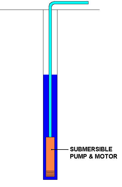
Submersible. Submersible pumps are installed completely underwater, including the motor. The pump consists of an electric motor and pump combined in a single unit. Typically the pump will be shaped like a long cylinder so that it can fit down inside of a well casing. Although most submersibles are designed to be installed in a well, many can also be laid on their side on the bottom of a lake or stream. Another common installation method for lakes and rivers is to mount the submersible pump underwater to the side of a pier pile (post). Submersibles don't need to be primed since they are already under water. They also tend to be more efficient because they only push the water, they don't need to suck water into them. Most submersible pumps must be installed in a special sleeve if they are not installed in a well, and sometimes they need a sleeve even when installed in a well. The sleeve forces water coming into the pump to flow over the surface of the pump motor to keep the motor cool. Without the sleeve the pump will burn up. Because the power cord runs down to the pump through the water it is very important that it be protected from accidental damage. You wouldn't want a boat tangled up in the cord or a snapping turtle to bite through it!
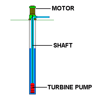
Turbines and Jet Pumps. A turbine pump is basically a centrifugal pump mounted underwater and attached by a shaft to a motor mounted above the water. The shaft usually extends down the center of a large pipe. The water is pumped up this pipe and exits directly under the motor. Turbine pumps are very efficient and are used primarily for larger pump applications. They are typically the type of pumps used on municipal water system wells. When you see a huge motor mounted on its end over a well, that is most likely a turbine pump. I use turbine pumps for large parks and golf courses where we are pumping from lakes. The turbine pump is mounted in a large concrete vault with a pipe connecting it to the lake. The water flows by gravity into the vault where it enters the pump. The pump motors are suspended over the vault on a frame. I usually use two or three different sized pumps side-by-side to handle different flow combinations. A jet pump is similar to a turbine pump but it works by redirecting water back down to the intake to help lift the water.
Pressure vs. Flow
The performance of a pump varies depending on how much water the pump is moving and the pressure it is creating. This is an important relationship not only because it determines whether the pump is suitable for your irrigation system, but also because it is these pump characteristics which allow you to control the operation of your pump. More on controls later. For now, the primary relationship to understand is that as the flow INCREASES, the pressure DECREASES. Here are the standard formulas used to estimate flow, pressure, and horsepower for all electric pumps. Note: these formulas have been simplified to assume a pump efficiency of 55% which is a good average figure to work with if you don't know the exact efficiency of your pump. Pressure for pumps is always (in the U.S.A. that is!) measured in feet of head, one foot of head is equal to 0.433 pounds per square inch. The formula is:
FT.HD. = HP x 2178 / GPM
GPM = HP x 2178 / FT.HD.
HP = GPM x FT.HD. / 2178
HP is brake horsepower
GPM is gallons per minute of flow
FT.HD. is pressure in feet of head (PSI x 2.31 = FT.HD.)
Selecting a Pump
Here's the basic procedure to follow if you're selecting a pump for a new irrigation system. This is presented here as an overview to help you see where the tutorial is going...
- Estimate your flow (GPM) and pressure (feet of head) requirements and select a preliminary pump model to use. The remainder of this tutorial will show you how to do this.
- Using your preliminary pump information, create a first draft irrigation design.
- Once you have a first draft of your irrigation you may be able to fine tune your pump selection based on that design. Would a different pump lower your irrigation costs or better fit your irrigation system design? Return to the pump selection process and re-evaluate your pump selection. Make your final pump selection.
- Return once again to your irrigation design. Can it be fine tuned to better match your final pump selection? Make any necessary adjustments.
Although this method requires considerable effort it will give you an excellent balance between pump and irrigation system, leaving you with a very efficient irrigation system!
Pump Pressure
A Brief(?) Lesson in Hydraulics
This is going to be incredibly boring, but necessary, so hang in there!
In the USA the pressure output of pumps is measured as "feet of head", which is normally shortened down to the term "feet head" and abbreviated as ft.hd.. If you need metric measurements you'll want to make reference to the Conversion Formulas where you'll find the necessary information for converting to your favorite measurement system!
Feet of head is really pretty easy, it is simply height of elevation. As everyone knows, water is pretty heavy. (Try carrying a 5 gallon jug of water up a flight or two of stairs!) That weight of the water is what creates water pressure! Think of a tall column of water. The "water pressure" at the bottom of that column is simply the total weight of all the water in the column above the point where you are measuring it. In fact, at any point in the column the water pressure is equal to the weight of the water above that point. So as you move up toward the top of the column the water pressure decreases. Inversely, just like in the ocean or a swimming pool, the deeper you go, the greater the water pressure! That greater pressure is what makes your ears hurt if you dive down to the bottom of a deep swimming pool!
In the USA pressure is normally expressed as "pounds per square inch" (PSI). See the weight connection? It's pounds per square inch, the weight of the water! Well, for pumps we simplify that even more by measuring the pressure (or weight) as feet of water depth! Now that's really simple! The water pressure in feet head is just the depth of the water in feet above the point at which the pressure is measured.
Example: Let's say you have a swimming pool that is 8 feet deep. At the very bottom of the pool the water pressure will be equal to 8 feet of head. Pretty simple! If you want to know the pressure in PSI you can convert it by multiplying feet head times 0.433. So the pressure in PSI would be 8 ft. hd. x 0.433 = 3.46 PSI. If you swam under water at a depth of 5 feet below the surface then the water pressure on your body would be 5 feet head or 2.17 PSI. The Titanic rests on the sea floor at a depth of 12,600 feet below the surface. Therefore the pressure on the hull of the Titanic is 12,600 feet of head or a bone crushing 5,456 PSI! Consider that the plastic pipe in your sprinkler system will burst at somewhere around 300 PSI of pressure!
Ok, now the difficult part. Since water is essentially a non-compressible liquid it exhibits the unique trait of transferring pressure horizontally when in a confined space. What this means is that water in a pipe exhibits the same pressure as it would if the pipe were perfectly vertical, even if the pipe isn't. The best way to demonstrate this is with a picture.
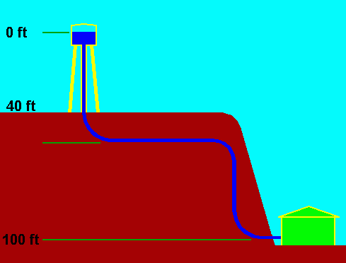
In the picture above the water pressure in the water tank at the top of the water level is 0 feet, or 0 PSI. This is because there is no water above it to create pressure. (Yes, I know there would be a small amount of water pressure due to the air pressure above the water, but let's try not to confuse things. This is hard enough to understand! So we're going to say that the water pressure at the water surface in the tank is 0 feet head. Ok?)
The ground level is 40 feet below the water level in the tank. Therefore the water pressure at ground level is 40 feet of head, or about 17 PSI. So far, pretty straight forward.
Now the hard to understand part. The water enters the house at a level 100 feet below the water level in the tank. So the static water pressure at the house is 100 feet of head, or about 43.3 PSI. Note that I said "static" pressure. So now you're likely wondering how this could be? The water level is not just 100 feet above the house there is also easily 180 feet of pipe between the tank and the house! The answer is that distance does not matter when the water is static (not moving) in the pipes. Because the water is a non-compressible liquid it transfers the pressure horizontally along the pipe route for pretty much any distance without any lose of pressure! If we measured the pressure with the water flowing the pressure would be termed "dynamic pressure". With the water in a dynamic state (flowing in the pipe) the water would loose pressure due to friction on the sides of the pipe and we would get a lower pressure reading at the house. But static pressure means no flow, no friction, and no pressure loss! Read that last sentence again! Think about it for a second, go back look at the picture again if you need to. It makes sense if you think about it. Our professor spent a week drilling this concept into us back in college and a lot of people in the class never did understand it! So if you still don't get it don't feel bad and don't get discouraged! Just continue on with the next paragraph.
In most cases we measure water pressure in the static state when designing irrigation systems (or any other water piping system for that matter). Then we use calculations to figure out the friction loss that will occur in the pipes and subtract it from the static pressure to arrive at the dynamic pressure. Why not just turn the water on and measure the dynamic pressure with the water flowing? It would seem that then we would not have to prepare a separate calculation for friction loss, right? Well, that is correct, however dynamic pressure is very difficult to measure. You have to get the flow just right and then hold the flow at that level for a minute or two while the pressure stabilizes. This is a real pain in the rear to do and not nearly as easy as it sounds! Plus, what if the pipe isn't installed yet? Then you can't measure the dynamic pressure at all. So, the result is that we almost always will work with static pressures. Its just easier, and who wants to do it the hard way?
Now go back and look at that picture above again. As the water flows to the house the water level in the tank will go down. So the elevation of the top of the water in the tank will not be as high above the house. When the tank is almost empty the difference might be only 95 feet. So the water pressure would also be lower. This happens all the time and is normal! If the elevation varies, then so will the water pressure. I know I keep saying the same things over and over in different ways, but I'm trying to drive home some important but hard to understand principles! My apologies if you got it the first time through and are getting bored!
Still confused? Don't worry about it, just follow through the procedures that follow and you'll be alright even if you don't fully understand why you're doing some of these things! Just remember that when I use the term "feet head" I'm talking about water pressure and whenever you measure water pressure with a gauge you need to turn off the water.
Wake Up!!
I know it's boring!!! Hang in there!
If you're planning to use a booster pump jump down to the heading Booster Pumps. Everyone else just continue on...
The following is oriented toward wells. If you don't pump out of a well don't panic, just substitute river, lake, pond, spring, mud-puddle, or whatever for "well" in the following procedures. "Top of well" would be the high water level of the river, lake... etc. Ok, that was easy enough, right? Let's move on...
First you will need to find out the "Dynamic Water Depth" of the water in your well. Dynamic Water Depth is the depth of the water below the top of the well, in feet, when the pump is running. OK, I know what you're thinking- "Jess, you idiot, if I don't have a pump yet how am I supposed to know what the water level is when the pump (which I don't have yet!!) is running?!!!" Well, of course you're right, but as you probably guessed, there is a solution. When a well company drills a new well they insert a temporary pump to "break in" and test the well. They refer to this as "developing" the well. As part of this process they also measure the Dynamic Water Depth of your new well at various pumping rates. Your pump company should have a record of this information which they can give you. One warning- you really should have the test repeated if the well is more than 5 years old. Water levels often drop over time. By the way, if you're not going to be pumping from a well just use the lowest "dry year" water level of your water supply in place of the Dynamic Water Depth. Note that the term "draw-down" is often erroneously used in place of Dynamic Water Depth. I often do this myself. So be sure to clarify when talking to your pump company. When the pump is running, the water level in the well drops below the water table. It may drop a few inches or more than 100 feet depending on the type of soil (or rock) the well is drilled into. Often the water level in wells drilled into rock will drop well over 100 feet when the pump is running, as the water can't easily move into the well from the surounding rock. At any rate, the real definition of "draw-down" is the distance the water drops in the well when the pump is running. But keep in mind that many people interchange the terms draw-down and Dynamic Water Depth. See the diagram below.Now you need to figure out the "Elevation Difference" between the top of your well and the highest point in the area to be irrigated. That is, how much higher (or lower) is the highest point in the irrigated area than the top of the well. This may be a negative number if the well is higher than the irrigated area. See the drawing below.
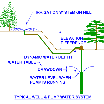
Irrigation System operating pressure. There is one additional ingredient you need to add, which is the pressure to operate the irrigation system. This pressure will be calculated as part of the irrigation design process and if you have a design already it should be noted on the irrigation design. If not, ask the designer what it is, he/she should know. (Note that the emphasis here is on should, as opposed to does. Way too many designers don't have a clue about pressures, which is a big sign that you better take a long, hard look at that design!). If you have an existing irrigation system that you want to add a new pump to, then you can try measuring the water pressure with a gauge at the point where you plan to tap the new pump into the system. This is one of those unusual cases where you want to measure the dynamic pressure, not the static pressure. So when you measure the pressure make sure that one of the irrigation system valves turned on and the sprinklers are running (run the largest circuit, the one with the most sprinklers).
Chances are you don't have an irrigation system yet, or even a design. In this case you will need to make an "educated guess". The following table will help you with your guess:
|
Drip Irrigation |
= |
70 feet head (30 PSI) |
|
Spray Type Sprinkler Heads |
= |
93 feet head (40 PSI) |
|
Rotor Type Sprinkler Heads |
= |
104 feet head (45 PSI) |
Remember, the values above are estimates. Dependent on your actual design you may need more or less pressure. You should design your irrigation system and adjust these values for the actual design before purchasing a pump! Spray sprinklers feature a steady fan shaped pattern of water. Rotors type sprinklers are used for larger areas and feature streams of water that rotate around the sprinkler. See the sprinkler features page of the Sprinkler Irrigation Tutorial for more information.
To finish up your pressure requirement calculations you simply add the values of the Dynamic Water Depth, elevation head, and operating pressure head together to get the total head required. Remember that all the values should be in feet of head, not PSI!
Example: You measure a Dynamic Water Depth of 25 feet in your well. The irrigation system is 10 feet higher than the top of the well. Your going to use rotor type sprinkler heads so you select an operating pressure of 104 feet head. Your total head required would be 25 + 10 + 104 = 139 feet of head!
Booster Pumps
As you remember, booster pumps are used to increase the water pressure. Therefore the required booster pump pressure is simply the desired pressure minus the existing pressure. Just remember the pressures must be expressed in feet of head, not PSI!
PSI x 2.31 = feet head
Feet head x 0.433 = PSI
Example: The existing pressure in the water company mainline you will use to supply water for your sprinkler system is 35 PSI static. (Static means the pressure is measured with all water shut off, no faucets running, ice makers shut off, no sprinklers on, etc. Except for a few rare situations this is the way you should always measure the pressure. You will get a lower and inaccurate pressure reading if water is flowing through the pipe.) Where was I? Oh yeah, you have 35 PSI existing pressure. But you want to use rotor type sprinkler heads and need 45 PSI for them to operate correctly. So you decide to add a booster pump to create more pressure. The pressure increase needed is 45 - 35 = 10 PSI. But wait, the pressure needs to be expressed in feet head, not PSI! So convert PSI to feet head. 10 PSI * 2.31 = 23.1 feet head. That wasn't difficult at all!
Selecting a Pump
By the way, if you call your pump dealer and give him the feet head (or even the PSI) and GPM you want to pump, he (she?) will figure out which pump you need. This is the best way to select a pump, as the dealers know their pump lines much better than you. They may suggest a pump you don't even know about. But for those who want to be educated consumers, here is how to do it yourself!
Pump Curves
A pump curve is a simple graph which shows the performance characteristics of a particular pump. Pump curves are created by the pump manufacturer based on test results of the various pump models the manufacturer produces. The pump manufacturer should be able to provide you with performance curves for the pumps you are considering. Remember, there is always an inverse relationship between pressure and flow. Higher pressures mean lower flows. Lower pressures result in higher flows. Here's a sample pump curve for study:
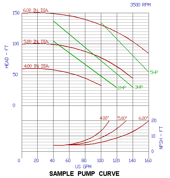
OK, that was a big help. Now how in the world do you use the thing? What's NPSH? Glad you asked! Here's a step by step guide to the pump curve above.
Each pump curve typically reflects a single model of pump made by the manufacturer. At the top right of the chart you will notice it gives the pump speed, in the chart above this is 3500 RPM. It is said that higher speed pumps wear out faster, but to be honest, I have never noticed a difference. I pretty much ignore the speed and try to select the pump with the best performance for my needs.
For each model there are two variables which effect the pump performance. The first is the horsepower of the motor attached to the pump. Remember, what we commonly refer to as a pump is actually a pump and motor. The pump is the part that moves the water, the motor is the part that moves the pump! Most pumps can be attached to several different sizes of motor. Bigger motors mean more volume and pressure.
The second variable is the size of the impeller. As you remember the impeller spins inside the case and this is what moves the water. Larger impellers fit tighter in the case leaving less room for slippage. This results in higher pressures. But you don't always want higher pressures, as pressures higher than what you need just waste energy!
Look at the left side of the curve and you will see a label HEAD - FT and numbers starting with 0 and increasing as you move up the chart. This is the pressure that the pump is capable of producing, measured in feet of head (not PSI!). The bottom of the curve is labeled US GPM. This is the flow that the pump produces.
Finding the proper pump is just a matter of selecting a model and size that will produce both the head and GPM that you need. To do this you select the horsepower and impeller size that will give you the desired performance.
The curves.
Notice the red color curved lines (the top one in the pump curve above is labeled "6.00 IN. DIA."). These represent the various impeller sizes. Now notice the green color straight lines which intersect the impeller curves (the top one in the pump curve above is labeled 5 HP). These lines represent the motor horsepower ratings available for this pump. Together the impeller curves and horsepower lines represent the best performance the pump is capable of if that horsepower or impeller size is selected. Some pump curves do not have horsepower lines, and some pump curves combine the horsepower and impeller lines into one single line. This is usually because the pump only is available with one motor, so you don't get to select the horsepower. The pump may also only come with one size of impeller, so you will only see a single line on the entire pump curve!
To use the curves you select the pressure you want on the left and then move horizontally across the chart to the vertical line that corresponds with the flow (GPM) that you want. You then select an impeller size curve and horsepower line that are above this point to determine the impeller size and horsepower you will need for your pump.
The following examples are based on the pump curve above.
Example #1: You want a pump that produces 125 feet of head while pumping 100 GPM. Start at 125 ft. hd. on the left of the pump curve. Now move straight across the curve to the right until you reach the line that goes down to 100 GPM on the bottom of the curve. From the point where the two lines intersect move up the chart to see what horsepower pump will be needed. In this case a 5 HP will be needed as the next horsepower line above our intersection point is the 5 HP line. Likewise, the impeller curve must also be higher in the chart than our line intersection, so a 6.00 IN. DIA. impeller will work.
Example #2: For 70 ft. hd. and 80 GPM. Make a mark at the point where the horizontal 70 ft. hd. line intersects the vertical 80 GPM line. This point is just above the 2 HP line, so a 2 HP pump will NOT work. We will need to use a 3 HP motor. The next higher impeller size is 5.00 IN. DIA. so we could use that impeller (but we might not, see "custom impellers" below).
Custom impellers. Pumps can be ordered with custom impeller sizes. This often does not cost much more than a "off the rack" pump, but it does take longer to get the pump since they need to custom build it! Almost all of the pumps I use have custom impeller sizes. To determine the custom impeller size you simply draw a new impeller curve through your ft. hd./GPM intersection point so that the curve is parallel to the other impeller curves. Then you determine the impeller size by comparing your new curve with the other impeller curves. For example, if your new curve is midway between the 5.00 inch curve and the 6.00 inch curve then you would need a 5.50 inch impeller! The good news is that you don't really need to do this, when you custom order a impeller the pump manufacturer will ask you what your feet head and GPM requirements are and they will calculate the best impeller size for you!
Pump Efficiency
On many pump curves you will see an additional set of ellipses labeled "efficiency" or simply with percentages labeled on them. For clarity I left these off of the example pump curve. These ellipses indicate the efficiency of the pump. To use them you simply look for the smallest ellipse that your line intersection point is inside. This is the efficiency at which the pump will operate. The higher the efficiency the better! A high efficiency pump uses less energy ($$$) to operate than a low efficiency pump. If possible, it is best to avoid any pump that has an efficiency of 55% or less. 55% efficiency is the industry standard used to estimate the performance of a pump when the actual efficiency is unknown.
Read the Manual
All pumps have oddities and special and unique requirements. Before installing a new pump always read the Owner's Manual. Please...?
Pump Controls
When I was a child, my parents owned a one room fishing cabin on the banks of the Rogue River in the town of Shady Cove, Oregon. This was a pretty primitive place, and our source of water was a small 120 volt electric pump in the river. When we needed water we simply plugged in the extension cord that ran to the pump and moments later, after a few gurgles and burps, the water would start flowing from the hose. Every once in a while we would get a bonus, and a small fish would come out too! To turn the water off we simply unplugged the cord. This is an example of the most basic of pump control systems, and yet all pump controls are no more than a variation on this same procedure. The pump is started and stopped by turning on or off the power supply!
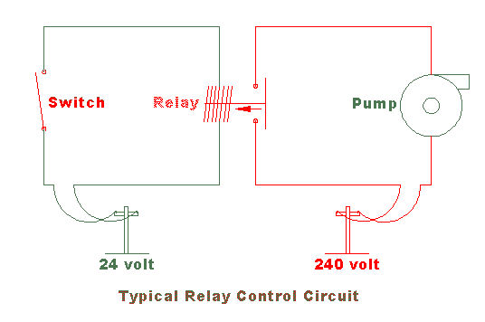
The next step up in pump control is to get rid of the plug and outlet and use a permanent switch to turn on and off the power flow. Some small pumps are stopped and started in exactly this way. But with the higher voltage and amperes commonly used for irrigation pumps a simple switch will not be practical. The switch would have to be huge to handle the load. Add to this the safety problems that develop when you add water to the equation. While 110 volts can kill you, contacting it with dry hands will likely only give you a bit of a "bite". Grab that same voltage with wet hands and there is a good chance your heart will stop, or at the least you will wish you had stayed in bed that day! Water makes your skin a much better conductor of electricity. Remember that little childhood trick your friends pulled, involving the 9-volt battery and your tongue? If you press the battery terminals on your skin nothing much happens. But lick your skin before trying it (I don't recommend sticking the battery terminals directly on your tongue!) and you will hear and possibly feel the spark jump! That's what water does with 12 volts and a fraction of an amp. Believe me when I tell you that the 24 volts and 2.5 amps put out by most automatic irrigation controllers will make you say some pretty unnice things if you grab the wrong two wires with wet hands. Imagine, then, the effect if you increase the voltage to 240 volts and 15 amps! (By the way, its the amps that kill you, not the voltage!) For this reason most pump control circuits are designed using a relay circuit that isolates the user from the pump voltage. The relay circuit is like a messenger. You tell the relay to start the pump and the relay starts it for you. Most relays use 12 or 24 volts, a few use 120 volts. For example, the controls for spas usually use a 24 volt relay circuit because the manufacturers know you're going to be turning them on and off with wet hands.
Automating the Control Circuit
To automate the control of the pump you simply replace the manual switch in the circuit with an automatic switch. There are several types commonly used.
- Timer. Any electric timer can be used to turn the pump on and off at predetermined times. With the right voltage relay, you could even hook it up to your computer!
- Pressure Switch. Most well pumps are controlled by a pressure switch. The pressure switch turns on the pump when the pressure drops in the pipes, and turns it back off when the pressure gets too high. A typical installation will have a pressure tank which stores pressurized water so that the pump doesn't cycle on and off rapidly due to pressure changes. The tank acts as a reservoir to stabilize the pressure in the system. Most pressure switches are adjustable, you can modify the on and off pressure settings within a limited pressure range, usually 20 to 45 PSI.
- Irrigation Controller. Most irrigation controllers have a pump start circuit built into them. You simply connect the wires that go to the switch in the diagram above to the controller pump start terminals, and the irrigation controller will turn the pump on whenever it turns on a valve. Do not hook up the controller to an existing relay circuit. In other words if your pump already has a low voltage starter circuit with a relay you will need to install a new one for the irrigation controller. The controller has it's own 24 volt AC power source, so if you hook it up to an existing circuit the irrigation controller may be damaged. If you don't understand electrical circuits get an electrician to wire it for you!
- Flow Switch. Flow switches are sometimes used on booster pumps. When the switch detects flow in the pipes it turns on the pump. So if you open a sprinkler valve, the water would begin to flow, and the pump would come on. This only works if the water is already pressurized and you want to use the pump to increase the pressure. An example would be a sprinkler system hooked up to the local water company pipes that needs more pressure than the water company provides.
- Combination of one or more of the above switches. It is very common to combine one or more of the switches above so that the pump is turned on or off by any of several different events. A very common application is one relay controlled by both a pressure switch and a manual override switch, and a second relay operated by the irrigation controller. I often will add a flow switch to the irrigation controller relay, setting it to turn OFF the pump if there is no flow. For example, if one of the automatic valves fails to open when the controller tells it to, the irrigation controller would force the pump to continue running, even though there was no water flow! The pump would then over heat, since it uses the continuous flow of water through it to remove the heat, and the bearings would melt.
Technical note: In order to simplify the pump formulas I have factored a pump efficiency of 55% into the value of the formula constant (2178). This is pretty standard procedure, and is a relatively conservative value. Although a new pump will almost always perform better, remember that the performance will drop with time as the pump begins to wear out.
You Can Help!
Please consider helping support the cost of providing these tutorials online and keeping them free of advertising. The support level suggested is much less than you would pay at a bookstore for a book on this subject and you get the satisfaction of knowing you helped place some truly useful information on the internet! See my support page for more information and a list of "bonus information" I provide for tutorial supporters. Don't forget to look over the other irrigation related tutorials at my homepage.
Comments? Questions? Product Data & Reviews More Irrigation Tutorials!
|
|
Jess Stryker's Irrigation Tutorials |